Oct 24, 2026Technical Articles & Engineering Insights
OBC-Battery Datasheet Comparison: The Numbers That Decide Compatibility
An OBC and a battery pack each come with a datasheet - but compatibility is decided by four numbers that must be read side by side. Here is how to compare them before committing to a design.
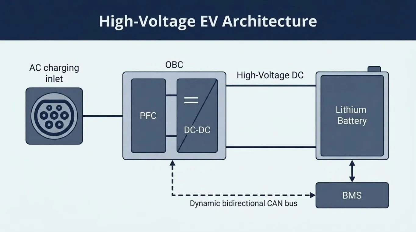
When an on-board charger fails to match a battery pack, the cause is rarely a mystery part. It is usually a number on one datasheet that was never compared against the corresponding number on the other. Voltage windows, current limits, power curves and CAN registers each live on a different page - and compatibility only exists where all four line up.
This article is a datasheet comparison guide: what to read on the OBC side, what to read on the battery side, and which values must be placed next to each other.
Number 1: The Voltage Window vs the Voltage Window
Both datasheets quote a voltage - but not the same one. The OBC datasheet gives its output voltage range (minimum to maximum) that it can regulate; the battery datasheet gives minimum discharge voltage to maximum charge voltage across the state-of-charge range. The rule is that the OBC's output range must contain the battery's full range. If the pack tops out at 420 V and the charger caps at 400 V, the last portion of the charge never happens - and the charger will sit at its limit, running hot, for the whole top-up. A charger spec that quotes only nominal voltage tells you nothing; ask for the window.
Number 2: Battery Charge-Current Limit vs OBC Output Capability
The OBC can push current; the pack decides how much it will accept. Compare the OBC's maximum output current at the relevant voltage against the battery's maximum continuous charge current - and often a per-cell C-rate that translates to a pack limit. The pack limit governs: a 6.6 kW charger delivering into a pack that accepts only 3 kW of charge adds cost and weight without shortening the session. Confirm the pack's allowed current at both low and high state of charge, because many BMS profiles taper the limit as the pack fills.
Number 3: The Charge Curve vs the Charger's Regulation Mode
A battery datasheet typically specifies a charge profile: constant current to a voltage threshold, then constant voltage, with a taper. A charger datasheet specifies whether it supports that profile and how it transitions. Two things must align: the CV threshold voltage, which is the exact voltage at which the charger must switch from constant current to constant voltage, and the taper behaviour, which is how the charger reduces current as the pack approaches full and at what point it terminates. If the charger's regulation mode does not follow the pack's required curve, the pack either undercharges or is stressed.
Number 4: CAN Registers vs CAN Register Map
Both sides list CAN messages, but a match requires the register level: on the OBC side, message IDs, signal names, scaling and byte order; on the BMS side, the same set for battery-side control. Matching the baud rate is not enough. The enable command, the setpoint registers, the status feedback and the fault codes all have to line up.

A Side-by-Side Comparison Template
Before committing to a design, place these on one page: output voltage range vs charge voltage range; max output current vs max charge current; CV threshold support vs required CV voltage; taper and termination vs required profile; CAN enable register vs BMS enable register; CAN status and fault registers vs BMS expected format; and thermal derating point vs ambient condition. Any row that cannot be filled is a risk carried into the prototype.
When the Numbers Do Not Line Up
Two outcomes are common. Either the charger is oversized for the pack, so the pack limits charge current and the extra charger power is never used - choose a lower power level or a pack with a higher charge limit. Or the charger is undersized for the duty cycle, so the pack would accept more but the charger cannot deliver it and the session runs long - step up a power level. Both are resolved on paper, not in the vehicle. That is the point of the comparison.
For the full selection process that surrounds these four numbers, see how to match an on-board charger to an EV battery pack.
Where Echelon Fits
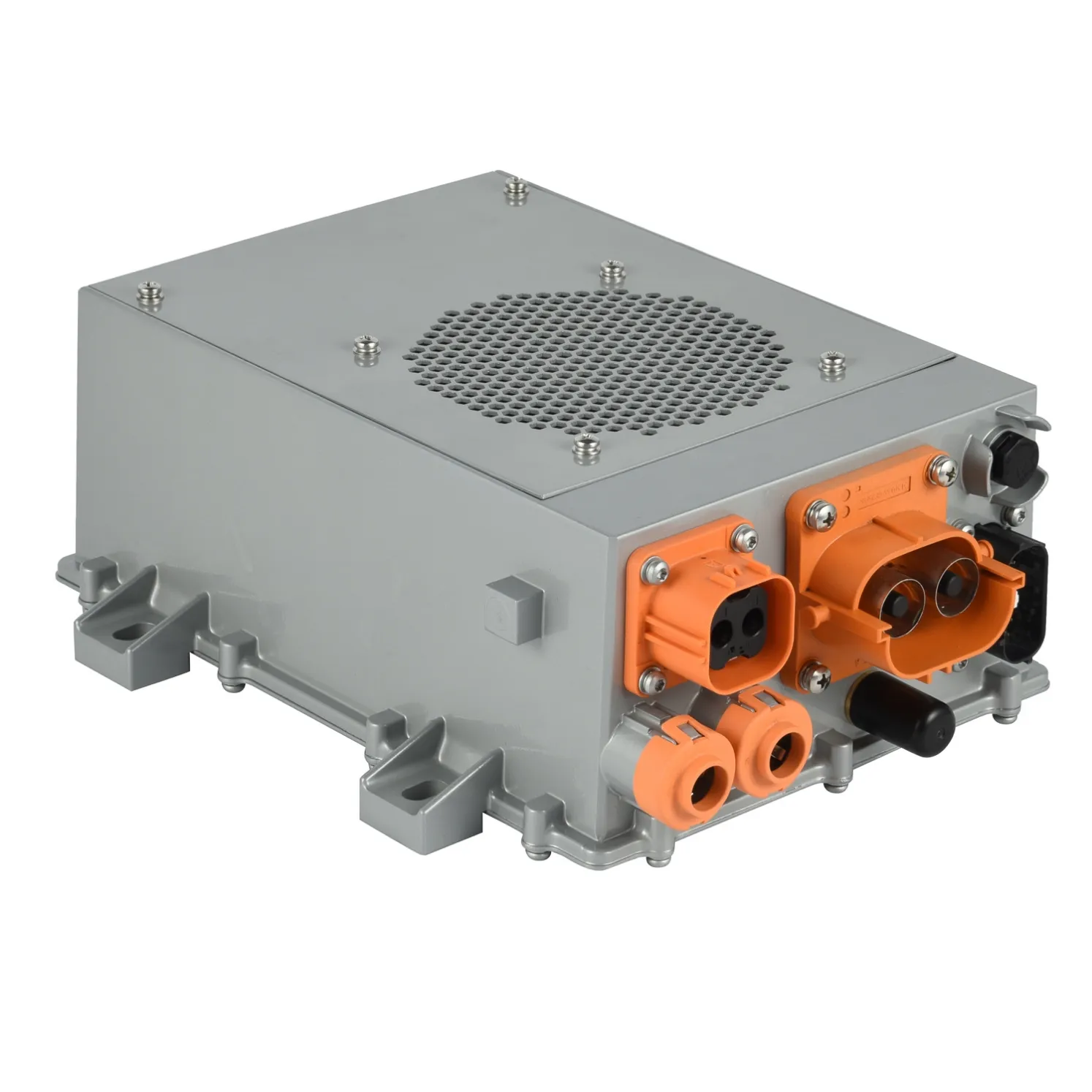
Echelon Energy Technology supplies on-board chargers with the datasheet detail needed for this comparison - full output voltage windows, current limits, CAN register maps and thermal derating curves. Representative units include the 3.3 kW OBC + 1 kW DC/DC and the 6.6 kW OBC + 1.5 kW DC/DC, with OEM/ODM customization under IATF 16949.
Conclusion
OBC-battery compatibility is a four-number problem: voltage window, current limit, charge curve and CAN registers. Read both datasheets side by side, fill the comparison table, and resolve mismatches before the prototype stage. Comparing an OBC against a battery pack? Share both datasheets with our engineering team for a compatibility review.
About Echelon Charger
Echelon Energy Technology specializes in onboard chargers, DC/DC converters, and integrated EV power solutions for commercial and specialty electric vehicles.
For technical discussions, product selection, or OEM/ODM cooperation:
Email: nancy@tici-energy.com
WhatsApp: +86 18114665311