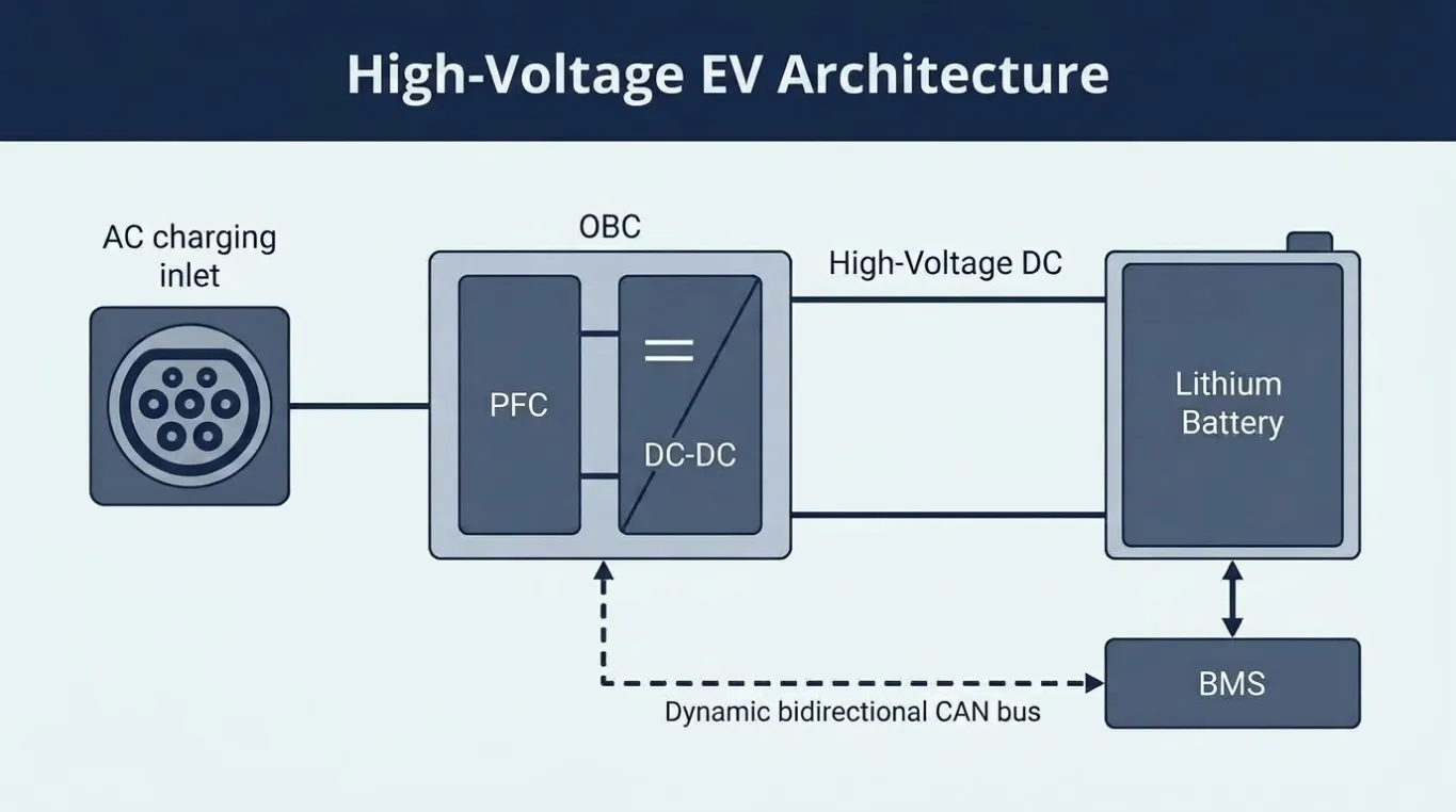
Sep 16, 2026Technical Articles & Engineering Insights
How to Match an On-Board Charger to an EV Battery Pack
Learn how to match an EV on-board charger with battery voltage, charging current, BMS CAN control, AC input and thermal limits for reliable vehicle integration.
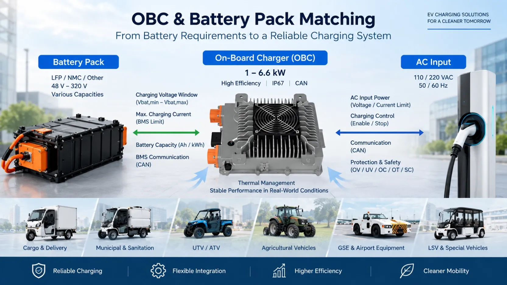
From an engineering perspective, OBC selection is an operating-window and system-integration problem. The charger must deliver the required voltage, current and power across the battery's charging range while remaining compatible with the BMS control strategy, AC input conditions and thermal limits of the vehicle.
Before OBC hardware and software parameters are finalized, several electrical and system-level factors should be evaluated.
1. Start with the Battery Charging Voltage Window, Not Nominal Voltage
A battery designation such as 72 V, 96 V or 320 V describes the nominal system voltage. It does not directly define the required OBC output voltage.
For charger selection, the more relevant parameters are:
- Vbat,min — minimum battery voltage at which charging may begin
- Vbat,max — maximum permitted pack charging voltage
- Ns — number of cells connected in series
- Vcell,max — maximum permitted charging voltage per cell
For a series-connected battery pack:
Vbat,max = Ns × Vcell,max
This is why two battery packs both described as “72 V” may require different OBC output settings.
Battery chemistry alone is also insufficient. Knowing that a battery is LFP or NMC does not fully define its charging voltage. The series-cell configuration and BMS charging limits must also be confirmed.
From the OBC side, the complete battery charging-voltage window should fall within the charger's regulated DC output range with appropriate engineering margin.
2. Check Whether the OBC Can Deliver Rated Power Across the Required Voltage Range
A charger rated at 3.3 kW or 6.6 kW should not automatically be assumed to deliver its rated power at every point within its output-voltage range.
The relationship between voltage, current and output power is:
Pout = Vout × Iout
For example, delivering 3.3 kW at 100 V requires approximately:
Iout = 3300 / 100 = 33 A
At 80 V, maintaining the same 3.3 kW would require:
Iout = 3300 / 80 = 41.25 A
If the OBC's maximum output-current capability is below this value, the charger becomes current-limited at the lower battery voltage and cannot maintain full rated power.
This distinction is important when evaluating a 3.3 kW or 6.6 kW on-board charger for a specific battery system.
Therefore, engineers should evaluate the OBC's voltage-current operating envelope, rather than comparing charger power ratings alone.
A useful specification should make clear both the regulated output-voltage range and the maximum available output current.
3. Battery Charge-Current Limits Must Be Matched to OBC Output Capability
The maximum permissible charging current is determined by the battery pack and its operating conditions, not by the OBC nameplate.
As an initial reference:
Ichg,max = C-rate × Battery Capacity (Ah)
For example, if a 100 Ah battery is permitted to charge at 0.5C, the corresponding charging-current limit would be approximately 50 A.
However, the allowable battery charging current is rarely a fixed value throughout the entire charging process.
The BMS may reduce permissible current according to:
- state of charge (SOC);
- cell temperature;
- pack temperature;
- cell-voltage spread;
- battery protection status;
- battery aging or operating strategy.
This means the OBC must not simply deliver its maximum available current whenever charging is enabled.
In a CAN-controlled system, the effective charging current may need to follow a dynamic limit requested by the BMS.
The selected OBC should therefore satisfy two conditions:
OBC maximum current ≥ required charging current
while
Actual charging current ≤ battery/BMS permitted current
These are different requirements and should not be confused.
4. CC/CV Describes Charger Regulation, but Not the Complete Vehicle Charging Strategy
OBC charging is commonly described as CC/CV — constant current followed by constant voltage.
During the constant-current stage, the charger regulates output current while battery voltage increases.
As the pack approaches its upper charging-voltage limit, charging transitions toward constant-voltage operation and current gradually decreases.
However, in a vehicle with active BMS control, the actual charging process may not follow one fixed CC/CV curve from beginning to end.
The BMS may continuously update:
- requested charging voltage;
- maximum charging current;
- charging enable/disable status;
- charging termination conditions.
The effective charger output is therefore constrained by several limits simultaneously:
OBC hardware capability
Battery/BMS request
OBC thermal condition
AC input capability
System protection limits
The OBC should operate within the most restrictive valid limit at any given time.
This is an important distinction between a basic standalone charger and an OBC integrated into a vehicle-level charging control system.
5. CAN Compatibility Requires More Than Matching the Baud Rate
“CAN supported” does not necessarily mean that an OBC can communicate correctly with a particular vehicle.
Before integration, the charger supplier and vehicle engineering team should confirm the actual CAN protocol requirements, including:
- CAN baud rate;
- message IDs;
- transmit and receive direction;
- DLC;
- Byte/Bit definitions;
- factor and offset;
- data range and units;
- message cycle time;
- charging enable logic;
- requested voltage and current;
- charger status feedback;
- fault definitions;
- communication timeout behavior.
Timeout strategy is particularly important.
If the OBC stops receiving a valid charging command from the BMS or VCU, the system needs a defined response. Depending on the vehicle control architecture, this may require output-current reduction, charging shutdown or entry into a communication-fault state.
Communication behavior is therefore part of charging-system safety and control, rather than simply a software-interface detail.
For a more detailed discussion, see How CAN Communication Improves EV Charger Integration with Vehicle Systems.
6. Charging Power Should Be Evaluated Against Battery Energy and Required Charging Time
OBC power should be selected according to both the battery and the vehicle's required charging time.
A first-order estimate is:
Charging time ≈ Battery energy to be replenished / Average battery-side charging power
However, dividing battery capacity directly by the OBC's rated power normally gives an optimistic result.
Actual battery-side charging power is affected by:
- charger conversion efficiency;
- battery voltage during charging;
- battery charge-current limits;
- BMS power reduction;
- AC input limitations;
- thermal derating;
- current tapering near the end of charge;
- auxiliary loads operating during charging.
For this reason, a 6.6 kW OBC does not necessarily deliver 6.6 kW to the battery continuously throughout the complete charging cycle.
When charging time is a vehicle-level requirement, engineers should evaluate the expected charging profile, rather than relying only on OBC nameplate power.
7. AC Input Conditions Can Limit Battery-Side Charging Power
OBC-to-battery matching should not be evaluated only from the DC output side.
The AC source must also provide sufficient input power for the requested battery-side charging power.
Approximately:
Pin = Pout / η
where:
Pin = AC-side input power
Pout = battery-side OBC output power
η = OBC conversion efficiency
The actual AC input current will then depend on input voltage, power factor and operating conditions.
This becomes important when the same vehicle platform is intended for markets with different AC supply conditions.
If the AC source, inlet, cable or upstream protection cannot support the required input current, the requested battery charging power cannot be sustained even if the OBC itself is capable of the required DC output.
OBC selection should therefore consider the complete energy path:
AC source → OBC input stage → power conversion → DC output → battery pack
8. Thermal Derating Must Be Included in OBC Selection
A charger can satisfy the required voltage and current specifications on paper but still fail to maintain the expected charging power under actual vehicle conditions.
Power conversion generates losses, and those losses become heat.
At high ambient temperature or under restricted cooling conditions, internal component temperatures may approach their allowable limits. The OBC may then reduce output power to protect the power stage and other temperature-sensitive components.
This means:
Rated power ≠ guaranteed continuous power under every thermal condition.
For commercial and specialty EV applications, engineers should confirm:
- rated ambient-temperature range;
- cooling method;
- installation orientation;
- required airflow;
- thermal derating threshold;
- output behavior after derating begins;
- continuous-load capability under the intended installation condition.
For more detail on this issue, see How Heat Dissipation Affects On-Board Charger Performance Under Continuous Load.
This is particularly relevant for utility vehicles, agricultural vehicles, GSE and other EVs where the charger may operate in enclosed installation spaces or under demanding ambient conditions.
9. Protection Thresholds Should Be Coordinated with the Battery and Vehicle
Both the BMS and OBC provide protection functions, but their thresholds and control responses should be coordinated.
Typical OBC protections may include:
- input overvoltage and undervoltage;
- output overvoltage;
- output overcurrent;
- short-circuit protection;
- overtemperature protection;
- communication fault protection.
The BMS may independently monitor:
- individual cell voltage;
- pack voltage;
- charging current;
- cell and pack temperature;
- insulation or other battery-system conditions.
These protections should operate as coordinated layers.
For example, the normal maximum charging-voltage command should remain below the OBC's hardware overvoltage-protection threshold with suitable margin.
Similarly, normal BMS current regulation should occur before the system repeatedly reaches the OBC's hardware overcurrent protection.
Protection trips should remain fault responses, not become part of normal charging regulation.
10. Define the OBC–BMS Interface Before Prototype Integration
Before a charger sample is installed in the vehicle, it is useful to define clearly which system has authority over each charging function.
For example:
Function | Typical Control Consideration |
|---|---|
Charging enable | BMS / VCU command or defined charger logic |
Target voltage | Battery requirement / BMS command |
Current limit | BMS request + OBC hardware limit |
Charge termination | BMS / vehicle charging strategy |
Fault handling | OBC protection + BMS/VCU response |
CAN timeout | Defined safe-state behavior |
Thermal derating | OBC internal control with status feedback |
This interface definition helps avoid a common prototype-stage problem: the charger and BMS are electrically compatible, but their control logic does not behave as expected when integrated into the vehicle.
11. What Information Should Be Provided to the OBC Supplier?
Before hardware selection or software calibration, the vehicle manufacturer should ideally provide a charging requirement sheet containing the following information:
Parameter | Information Required |
|---|---|
Battery chemistry | LFP / NMC / other |
Cell configuration | Number of cells in series |
Nominal pack voltage | V |
Battery operating-voltage range | V |
Maximum charging voltage | V |
Battery capacity | Ah / kWh |
Maximum charging current | A |
Target charging power | kW |
AC input | Voltage / frequency |
Communication | CAN protocol / message definition |
Charging control | Enable and command logic |
Thermal environment | Ambient temperature / airflow |
Vehicle application | Utility EV / GSE / LSV / commercial EV |
Installation constraints | Space / mounting / connector requirements |
Providing these parameters before sample production allows the OBC supplier to determine whether an existing charger operating envelope is suitable and what parameters may require configuration.
For vehicle architectures that require both battery charging and low-voltage power conversion, an OBC + DC/DC integrated solution can also be evaluated during the system architecture stage.
This evaluation should be made at the architecture stage because integration affects not only packaging, but also high-voltage distribution, low-voltage output requirements, communication and thermal design.
OBC Selection Should Be Verified as an Operating Envelope
The most reliable way to match an OBC to an EV battery pack is to compare the operating envelopes of the battery, charger and vehicle system rather than matching nominal voltage labels.
The engineering review should verify:
Battery voltage window
→ within the regulated OBC output range
Battery allowable charging current
→ compatible with OBC current capability
Required charging power
→ achievable across the relevant battery-voltage range
BMS charging commands
→ compatible with OBC control and CAN strategy
AC input capability
→ sufficient for the required battery-side charging power
Thermal environment
→ allows the required continuous output without unacceptable derating
Protection and fault logic
→ coordinated between OBC, BMS and vehicle controller
Once these conditions are aligned, prototype testing can focus on validating the complete charging system rather than correcting fundamental specification mismatches after vehicle integration.