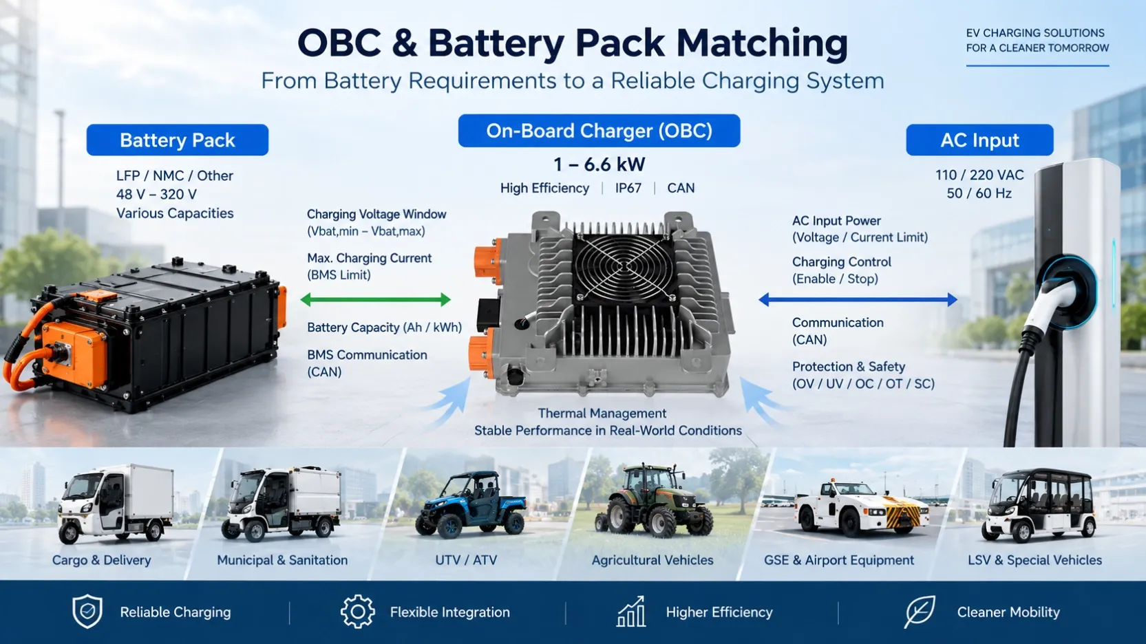
Sep 25, 2026Technical Articles & Engineering Insights
What Causes an On-Board Charger to Reduce Power During Charging?
Learn why an EV on-board charger may operate below rated power due to AC input, battery voltage, output current limits, temperature and protection conditions.
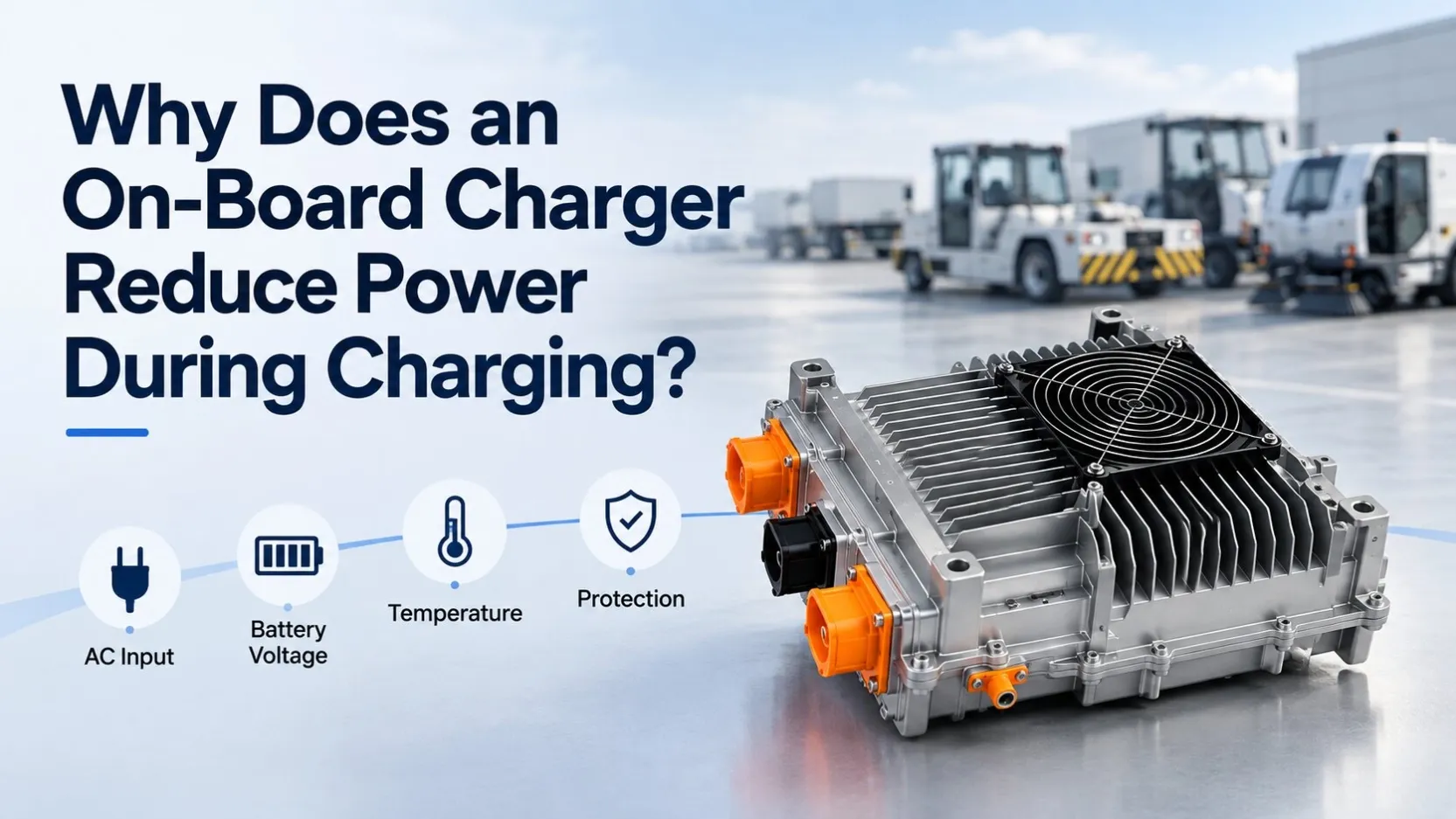
What Causes an On-Board Charger to Reduce Power During Charging?
A 6.6 kW on-board charger does not necessarily deliver 6.6 kW throughout the entire charging process.
This is an important point when EV manufacturers evaluate an OBC. Rated power describes one part of the charger's operating capability, but actual charging power also depends on the AC input, battery voltage, output current limit, temperature and protection conditions.
A practical way to understand this is to look at the operating envelope of an actual charger rather than only its rated power.
For example, one Echelon 6.6 kW OBC + 1.5 kW DC/DC integrated unit for a 96 V platform has an OBC output voltage range of 64–128 VDC, an output current range of 0–60 A, and a maximum efficiency of at least 93%.
These parameters already tell us something important:
Charging power must be considered together with voltage, current, AC input and operating conditions.
1. AC Input Voltage Can Limit Available Charging Power
One of the first parameters to check is the AC supply.
For this 6.6 kW OBC, the specified AC input range is 90–264 VAC. However, the rated output power is not the same across different AC input conditions:
- 6.6 kW at 220 VAC
- 3.3 kW at 110 VAC
The input current range is specified as 0–32 A.
This means that simply identifying a charger as a “6.6 kW OBC” is not enough when evaluating its actual performance in a vehicle.
The available AC supply must also be considered.
For vehicle manufacturers developing products for different countries or charging environments, this becomes especially important. The same OBC may operate at different maximum power levels depending on the available AC input.
Therefore, when selecting an OBC, a useful question is not only:
“What is the rated power?”
but also:
“Under what AC input condition is that rated power available?”
2. Battery Voltage and OBC Current Limit Work Together
The next factor is the battery-side operating voltage.
The same Echelon unit specifies:
Output voltage: 64–128 VDC
Output current: 0–60 A
Electrical power can be expressed as:
P = V × I
This relationship is important because an OBC cannot be evaluated by its power rating alone.
For example, if we use the specified maximum output current of 60 A:
At 64 V:
64 V × 60 A = 3.84 kW
At 80 V:
80 V × 60 A = 4.80 kW
At 96 V:
96 V × 60 A = 5.76 kW
At 110 V:
110 V × 60 A = 6.60 kW
These figures are calculations based on the published voltage and current limits; they are not a separate charging-control specification.
They illustrate an important engineering point: at lower battery voltage, the charger's maximum output current can become the limiting factor before its maximum power rating is reached.
Therefore, a 6.6 kW label should not be interpreted as meaning that the charger will deliver 6.6 kW at every battery voltage.
This is one reason why battery voltage range and charging current requirements should be checked together when matching an OBC to a battery pack.
3. Thermal Conditions Can Cause Power Derating
Temperature is another important reason why charging power may decrease.
For this OBC, the specified operating ambient temperature range is:
-40°C to +55°C
The unit uses forced-air cooling and is rated to IP67.
More importantly, the specification defines a specific internal thermal protection strategy for the OBC:
At an internal charger temperature of 85°C, power starts to decrease. At 90°C, the charger shuts down.
This is thermal derating.
Instead of continuing to operate at full output as internal temperature rises, the charger reduces power before reaching the shutdown threshold.
From a vehicle-integration perspective, this means cooling conditions matter.
Airflow around the charger, installation position, ambient temperature and heat accumulation inside the vehicle can all affect the thermal environment in which the charger operates.
A charger that reaches full rated power on a test bench should therefore also be evaluated under realistic installation and continuous-load conditions.
4. Power Derating and Protection Shutdown Are Not the Same Thing
These two conditions should not be confused.
Power derating means the charger continues operating, but at reduced power.
Protection shutdown means output is stopped when a protection threshold is reached.
The OBC specification includes protection against input under-voltage, input over-voltage, output under-voltage, output over-voltage, output over-current, short circuit and over-temperature.
For example, the specification states an output over-voltage protection threshold of ≥128 VDC. It also specifies that output stops when the maximum output current threshold is reached, while short-circuit protection stops the output and allows recovery after the fault is removed.
This distinction matters during vehicle testing.
If charging power changes unexpectedly, engineers should first determine whether the charger is operating within a normal power-limited region, undergoing thermal derating, or entering a protection condition.
These are different operating states and should not automatically be treated as the same type of charger fault.
5. An Integrated OBC and DC/DC Can Have Different Thermal Limits
Integrated power electronics add another consideration.
The example discussed here combines a 6.6 kW OBC and a 1.5 kW DC/DC converter in one unit.
The DC/DC section operates from 64–128 VDC and provides a 9–16 V output, with a rated output current of 110 A, a peak current of 132 A and rated power of 1.5 kW. Its specified maximum efficiency is at least 94%.
However, its thermal protection thresholds are different from those of the OBC.
For the DC/DC section, the specification states:
Power reduction begins at an internal temperature of 90°C, shutdown occurs at 105°C, and operation recovers automatically after the temperature decreases.
The OBC section, by comparison, starts reducing power at 85°C and shuts down at 90°C.
This demonstrates why an integrated OBC + DC/DC unit should not simply be treated as a single “power number.”
Each function has its own electrical operating limits and protection requirements.
6. CAN Communication Is Part of Vehicle Integration
The unit supports CAN Bus communication. Its signal interface also includes CANH and CANL, together with wake-up, DC enable, CC, CP, high-voltage interlock and electronic-lock related signals.
For an EV manufacturer, this means electrical power matching is only one part of OBC integration.
The charger must also interface correctly with the vehicle's control architecture.
However, the product specification alone does not define the complete CAN message strategy or BMS charging-control logic. Those requirements need to be confirmed according to the specific vehicle project.
This is especially important during prototype integration: charger voltage and power may be suitable while the vehicle-side communication and control requirements still need adaptation.
7. Rated Power Should Be Evaluated as an Operating Envelope
When comparing OBCs, it is tempting to compare products using one number:
3.3 kW, 6.6 kW, 11 kW...
But for engineering selection, the more useful approach is to evaluate the complete operating envelope.
Before selecting an OBC, EV manufacturers should confirm:
- AC input voltage and available input current
- Battery operating and maximum charging voltage
- Required charging current
- OBC maximum output current
- Thermal and installation environment
- Cooling conditions
- Protection thresholds
- CAN and vehicle-control interface requirements
A charger may have the correct rated power but still be unsuitable if one of these operating limits does not match the vehicle.
Conclusion
A reduction in OBC charging power does not automatically indicate a charger problem.
The actual charging power can be limited by the available AC input, battery-side voltage and current relationship, thermal conditions, or protection limits.
For example, the 6.6 kW OBC discussed here is specified for 6.6 kW output at 220 VAC but 3.3 kW at 110 VAC. Its output range is 64–128 VDC with a maximum current of 60 A, while thermal derating begins when the charger's internal temperature reaches 85°C.
For EV manufacturers, the key is therefore not simply to ask:
“What is the maximum OBC power?”
A better question is:
“Can the OBC deliver the required charging performance across the actual electrical and thermal operating conditions of the vehicle?”
That question leads to a much more reliable OBC selection and vehicle-integration process.
Evaluating an OBC for your vehicle project? Share your battery voltage range, charging power, AC input and CAN requirements with our engineering team to check a suitable configuration.