OEM & EV Application Insights
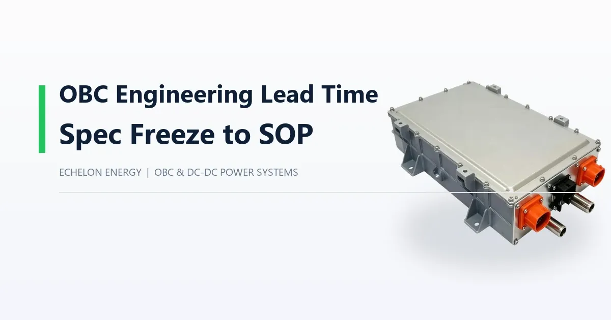
OBC Engineering Lead Time: From Specification Freeze to Start of Production
How long does a custom on-board charger take? This guide breaks OBC lead time into specification freeze, prototype, validation, pilot and production release.
"How long does it take?" is usually the second question after price, and it is harder to answer because lead time depends more on the program than on the supplier. A charger adapted from an existing platform and a charger designed from a clean sheet share almost no schedule.
This guide breaks the timeline into stages so a vehicle team can build a realistic plan and identify where the schedule risk actually sits.
The stages of an OBC program
Stage | What happens | What can extend it |
Specification freeze | Voltage window, auxiliary load, envelope, CAN matrix and validation scope agreed | Requirements still moving after this point |
Design and adaptation | Schematic, layout, mechanical and firmware changes | New enclosure, new isolation design, bespoke diagnostics |
Prototype build | Sample units built and bench-tested | Component lead times, build queue |
Prototype validation | Functional, thermal, environmental and endurance testing | Test failures requiring design change |
Vehicle integration | Charger installed and exercised in the vehicle | Harness or packaging issues found late |
Pilot build | Production-intent batch built and fielded | Outstanding design changes |
Production release | Tooling, end-of-line limits, change control | Tooling fabrication and qualification |
The critical point is specification freeze. Everything after it is execution; everything before it is negotiation. Programs that freeze late do not save time - they move the same uncertainty into the build and validation stages, where changes cost more.
What the specification freeze must actually contain
Battery nominal voltage and full charge voltage window
Pack capacity and required charge time
Available AC supply: voltage, phase, current
Auxiliary load list with continuous and peak values
Mounting envelope, orientation and cooling medium
CAN matrix and master/slave role
Target markets and the validation scope they imply
If any of these is provisional, the freeze is not a freeze. A charger built to a provisional voltage window frequently needs a power-stage change later, which is the most expensive kind of schedule slip.
Where the schedule usually slips
Voltage window clarified too late. A pack design change moves the charger requirement outside the selected platform's output range.
Auxiliary load discovered late. Adding a coolant pump or a tail lift pushes the DC-DC stage past its rating.
CAN matrix delivered late. Firmware mapping waits, and the vehicle integration window compresses.
Validation failures. Thermal or vibration issues found during testing require a design iteration and a new test cycle.
Tooling queued late. Tooling is ordered after pilot instead of in parallel with the last design changes.
The first three are entirely avoidable with complete inputs at RFQ stage. The last two are normal program risk and are the reason a schedule should carry contingency between validation and the pilot build.
Prototype hardware lead time versus engineering lead time
These are different clocks. Engineering lead time covers design, documentation and validation. Prototype hardware lead time covers material procurement and build once the design is released.
Programs often quote one number and plan against the other. A useful question at quotation stage is: what is the lead time for the first prototype set after design release, and what is the lead time for a repeat build after a design change? The second number is what determines recovery from a validation failure.
Compressing the schedule without adding risk
Start from a production-proven platform to remove the power-stage design stage entirely
Send the CAN matrix at RFQ stage rather than after platform selection
Run vehicle harness and mounting design in parallel with charger validation
Order tooling in parallel with the final prototype validation, with a change-window agreement
Agree the validation scope with the target market before testing begins
None of these shorten validation itself. They remove waiting between stages, which is where most schedule loss occurs.
Platforms that shorten the path to a prototype
Most schedule loss happens before the prototype build, while the electrical requirement is still being matched to hardware. A platform whose output window already covers the pack removes the design stage entirely.
Platform | DC output window | DC-DC stage | Fits best |
240-480 Vdc, 0-20 A | 9-16 Vdc, 1500 W, 110 A rated / 132 A peak | 400 V class vehicles on forced-air cooling | |
240-480 Vdc, 0-10 A | 14 V, 1000 W, 72 A | Cost-sensitive 400 V programs | |
200-470 Vdc, 0-32 A | 9-32 Vdc auxiliary rail | Three-phase sites, V2L/V2G, liquid cooling | |
64-128 Vdc / 240-480 Vdc | external DC-DC | Where the auxiliary supply already exists |
If one of these rows covers the pack and the auxiliary load, the program starts at the validation stage rather than the design stage, which is where most of the calendar time is saved.
FAQ
What is the longest part of an OBC development schedule?
Usually validation, and specifically any design iteration that follows a test failure. A first-pass validation on a reused platform is much shorter than a validation cycle that includes a redesign.
Can engineering and prototype build overlap?
Partially. Long-lead components can be ordered once the architecture is fixed, while detailed design finishes. Full overlap is not possible because the build follows the released design.
Does a pilot build add much time?
The pilot build itself is short; the value is in the field data it produces. Planning should allow for the pilot to run long enough to expose unit-to-unit variation.
For a program-specific schedule, share the voltage window and target milestones through our contact page, and see OEM/ODM cooperation for how the stages are structured.