EV System Integration & Architecture
PDU + DC-DC 2-in-1 with a Separate OBC: Why Split It This Way
Why some EV platforms combine PDU with DC-DC and keep the OBC standalone: thermal duty cycles, variant flexibility, HV routing and the interfaces to agree.
Most integrated power discussions assume the same split: combine the on-board charger with the DC-DC converter, and keep the power distribution unit separate. That is the arrangement most commercial vehicle programmes reach for first.
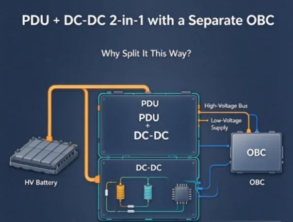
There is a second arrangement that deserves equal attention, and it appears on commercial and specialty electric vehicles where the charging power varies between variants but the auxiliary and distribution requirements do not: PDU and DC-DC in one unit, with the OBC supplied as a standalone part.
The two options solve different problems. Choosing between them is not a matter of which integration is more advanced - it is a question of where the thermal load sits, which part changes across a model range, and what the service strategy looks like. This article sets out the trade-offs so an architecture review can settle the question before the harness drawings are released.
What this architecture actually is
In a PDU + DC-DC 2-in-1 arrangement, the power distribution unit carries the HV junction, contactors, fuses, pre-charge circuit and service disconnect. The DC-DC stage converts the pack voltage down to the 12 V or 24 V auxiliary rail. Both live in one enclosure mounted close to the battery pack, while the OBC is a separate box mounted where the AC inlet is.
This is the mirror image of the more familiar OBC + DC-DC 2-in-1, where charging and auxiliary conversion share a housing near the charge port and the PDU sits separately at the battery junction.
Why an OEM would split it this way
The two loads have different duty cycles
The OBC is an intermittent, high-power load that only runs while the vehicle is plugged in. The DC-DC converter is a continuous, lower-power load that runs whenever the vehicle is awake. Putting both in the same enclosure forces the thermal design to satisfy both at once: the heatsink must handle the charging peak, and the airflow path must serve a converter that never stops. Separating them lets each unit be optimised for its own duty cycle.
The PDU belongs at the battery, the OBC belongs at the inlet
A PDU has to sit close to the pack's HV junction, the service disconnect and the contactor box. An OBC has to sit close to the AC inlet, because AC cabling is bulky and routing it across the vehicle is expensive. On a platform where those two locations are far apart - a rear charge port with a floor-mounted pack, for example - combining OBC with DC-DC forces long HV runs from the inlet to the battery area. Combining PDU with DC-DC keeps the HV path short and lets the OBC stay at the inlet.
One DC-DC and PDU serves every power variant
Charging power varies by market and model: 3.3 kW for entry variants, 6.6 kW or 11 kW for longer-range ones. The auxiliary rail and the HV distribution requirements usually do not vary with it.
If DC-DC and PDU are combined, one shared unit covers the whole range and only the OBC changes between variants. If OBC and DC-DC are combined, every charging-power variant needs its own integrated unit, which multiplies part numbers, the validation matrix and the spares inventory.
Service strategy separates cleanly
A PDU carries fuses and contactors - items a workshop may need to reach. An OBC is a charger that either works or is replaced. Keeping them in different boxes means a fuse replacement does not require opening the charger enclosure, and a charger replacement does not disturb the HV junction.
The auxiliary rail is often shared with other systems
On some platforms the DC-DC feeds more than the vehicle: a body builder's equipment, an upfitter's load, or a second auxiliary network. Placing DC-DC inside the PDU box makes those connections land at a single distribution point instead of at a charger mounted somewhere else.
What you give up
Splitting the architecture is not free. The costs are real and should be counted before the decision is taken.
Cost | What it means in practice |
Extra connectors | One more HV interface pair, plus its HVIL loop |
Extra harness | A separate HV run between the OBC and the distribution point |
Two enclosures | Two mounts, two brackets, two sets of fasteners |
Two CAN nodes | The network gains another node with its own diagnostics |
Assembly time | One more station operation on the line |
Two qualification scopes | Each unit needs its own environmental and EMC evidence |
The counterweight is that each cost is measurable and predictable, while the benefit - variant flexibility and thermal independence - compounds across a model range. On a single-variant programme the trade often goes the other way; on a platform expected to spawn several power levels, the split usually wins.
Which split suits which programme
Programme characteristic | OBC + DC-DC 2-in-1 | PDU + DC-DC 2-in-1, separate OBC |
Single power variant, short lifecycle | Preferred - fewer parts | Overhead not repaid |
Several charging-power variants on one platform | Every variant needs its own unit | One shared unit, OBC varies |
Charge port far from the battery junction | Long HV runs | Short HV runs |
Continuous high auxiliary load | Thermal design compromised | Independent thermal design |
Upfitter or body-builder loads | Connections split across two locations | Single distribution point |
Low-volume specialty vehicle | Fewer interfaces to manage | More interfaces for little gain |
The interface points that decide the schedule
Whichever split is chosen, four interface definitions have to be agreed before the harness is released. They are the same four in both arrangements, but the split changes who owns them.
HV interconnection and HVIL
Define the connector family, pin assignment and the HVIL loop for the link between the OBC and the distribution point. If both units come from one supplier, that link is an internal interface and the supplier can specify it. If they come from two suppliers, each side will assume the other is responsible unless it is written down.
Pre-charge and contactor sequencing
The PDU owns the pre-charge circuit. The OBC has its own internal capacitance. The sequence that charges the OBC's DC-link through the pre-charge resistor before the main contactor closes must be defined by the vehicle controller, and both units must tolerate the timing it produces.
Wake-up and enable logic
Which node wakes first, which signal enables the DC-DC, and whether the OBC can be enabled over CAN alone are architecture decisions rather than component decisions. They need to be settled with the network matrix, not after it.
Fault propagation
If the OBC reports an isolation fault, what does the PDU do? If the DC-DC drops out, does the OBC stop? A split architecture has more fault paths than an integrated one, and each one needs a defined behaviour.
What a split architecture asks of the OBC specifically
A standalone OBC in this arrangement carries responsibilities that an integrated unit can hide:
- Its own HV connector and HVIL loop, because it is now a discrete HV node rather than a subsystem inside another box
- Its own enclosure sealing to IP67, tested on its own
- Its own thermal path, with no shared heatsink and no shared airflow
- Its own EMC evidence, because a combined test result does not transfer to a different enclosure in a different location
- A stated relationship with the PDU's pre-charge circuit, which means the OBC must declare its DC-link capacitance
That last point is the one most often missed. A supplier who cannot state the input capacitance of their charger forces the vehicle team to over-size the pre-charge resistor, which slows every start-up.
Products that fit this architecture
Echelon supplies the two halves of this arrangement as separate units.
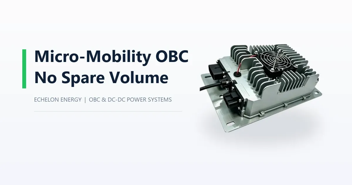
The standalone 6.6 kW on-board charger covers 96 V and 320 V platforms with 90-264 Vac input, CAN bus communication and IP67 sealing, for programmes where the auxiliary converter is specified elsewhere.
On the auxiliary side, the 1 kW DC/DC converter provides 9-16 Vdc output at 72 A rated and 86 A peak, 1200 W, in a 2.8 kg forced-air-cooled housing. The 10 kW DC/DC module covers higher auxiliary demand at 95% efficiency.
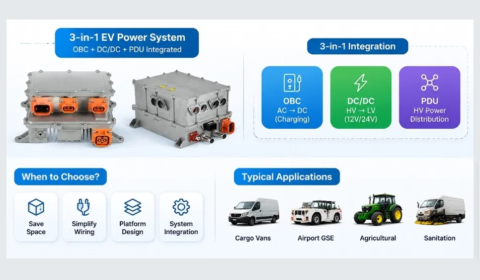
Where distribution is required in the same enclosure, the 3-in-1 OBC + DC-DC + PDU shows the same PDU and DC-DC stages in an integrated format and can serve as a starting point for a PDU + DC-DC configuration.
For a programme that needs PDU and DC-DC combined without the charger stage, the configuration is an OEM/ODM scope question rather than a catalogue item, because the PDU content - contactor rating, fuse set, pre-charge sizing, outlet count - is programme-specific.
What to send for an architecture review
To say whether this split works for a given platform, five inputs are enough:
1. Pack nominal voltage and full charge voltage window
2. Required charging power and the AC supply available at the depot or home
3. Auxiliary load list in watts, continuous and peak
4. Distance between the charge port and the battery junction, with the mounting envelope for each
5. Distribution requirements: contactor rating, fuse set, outlet count and pre-charge expectation
With those, the split can be assessed on packaging and thermal grounds before any commercial discussion starts.
FAQ
Why would an OEM put the PDU and DC-DC together instead of the OBC and DC-DC?
Because the PDU and the DC-DC share a location - both belong at the battery junction - while the OBC belongs at the AC inlet. When those locations are far apart, combining PDU with DC-DC keeps the HV runs short, and one shared unit can serve every charging-power variant on the platform.
Does splitting the OBC out increase cost?
It increases part count: one more connector pair, one more HV harness run, one more enclosure and mount, and one more CAN node. Whether that is repaid depends on how many charging-power variants the platform will carry. On a platform with three power levels, one shared PDU + DC-DC plus three OBC variants is usually cheaper than three integrated OBC + DC-DC units.
Who owns the pre-charge timing in a split architecture?
The PDU owns the pre-charge circuit, but the timing depends on the OBC's DC-link capacitance. The vehicle controller sequences it, so both units must be specified against the same number. Ask the charger supplier to state the input capacitance explicitly.
Can a standalone OBC use CAN-only enable control?
That depends on the platform's control strategy and on the charger variant. In the split architecture the OBC is a discrete node, so the enable method is defined with the network matrix rather than inherited from an integrated unit. Confirm it per variant rather than assuming.
Does an integrated unit's EMC evidence cover the separate units?
No. A combined EMC result belongs to the tested configuration. If the OBC moves into its own enclosure in a different location, it needs its own evidence for that installation.
About Echelon Charger
Echelon Energy Technology specializes in onboard chargers, DC/DC converters, and integrated EV power solutions for commercial and specialty electric vehicles.
For technical discussions, product selection, or OEM/ODM cooperation:
Email: nancy@tici-energy.com
WhatsApp: +86 18114665311