EV System Integration & Architecture
OBC and DC-DC for Micro-Mobility: Power in a Vehicle With No Spare Volume
On a micro-mobility platform the charger is a measurable share of the vehicle. Voltage class from 48 V to 96 V, converter sizing, the 110 V derating trap and thermal limits.
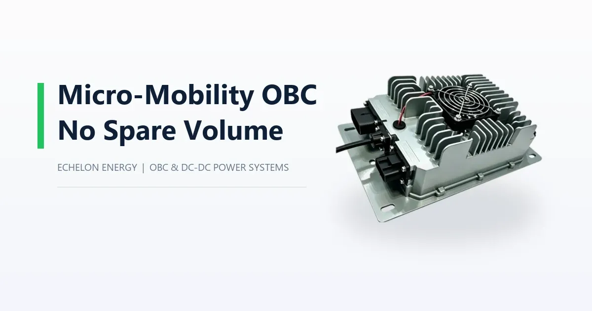
A micro-mobility vehicle is not a small car. That distinction matters more for power electronics than for any other subsystem, because the constraints scale differently.
On a 1.5 tonne van, a 6.5 kg charger is noise in the mass budget. On a 250 kg last-mile vehicle, the same unit is 2.6% of the vehicle before you have mounted it, cooled it or run a cable to it. The bay is smaller, the auxiliary load is smaller, and the charger power is smaller - but the ratio of charger to vehicle does not shrink with it. It grows.
That inversion changes the selection logic. Three parameters that dominate passenger-car charger selection become secondary, and three that rarely appear in a passenger-car specification become decisive.
What Stops Mattering, and What Starts
On a large platform, the conversation is about charging power, three-phase input and bidirectional capability. On a micro-mobility platform:
• Charging power is capped by the battery, not by the charger. A 4 kWh pack at 3.3 kW is already charging at 0.83C. Going to 6.6 kW buys very little total charge time, because the taper at the top of the curve eats the difference.
• Three-phase input is irrelevant. The vehicle charges overnight from a domestic socket in a garage, a depot or a kerbside outlet.
• Bidirectional operation is rarely a product requirement, because the auxiliary load is small and the pack has little energy to spare.
What takes their place:
• Volume and mass, as discussed above.
• Auxiliary load sizing, which is routinely over-specified.
• Input behaviour at 110 V, which is where more deployments fail than anywhere else.
Choosing the Voltage Class: 48 V, 72 V or 96 V
The choice is usually made by the drivetrain, but it has a direct consequence for the charger.
48 V keeps the whole high-voltage side below the 60 V DC threshold that many electrical safety frameworks use to separate low voltage from high voltage. That simplifies clearance, creepage, connector specification and technician qualification. A 48 V platform with a 1.5 kW OBC and a 500 W DC/DC covers a large share of low-speed and light-cargo vehicles, and the integration work is meaningfully lighter than at 72 V.
72 V and 96 V cross that threshold. The drivetrain efficiency and cable current arguments usually win - at the same power, a 96 V system carries two-thirds of the current of a 48 V system, which matters when the harness runs the length of a small vehicle - but the charger and its installation now sit inside the high-voltage rule set. Clearance to adjacent metal, connector rating, insulation monitoring and service procedure all change.
The practical point is that this decision is made once, early, and it determines which charger family you can even quote. A 48 V unit will not serve a 96 V platform. Confirm the platform voltage before comparing power levels, because the comparison is otherwise meaningless.
Sizing the DC/DC: Most Vehicles Ask for Less Than They Specify
The auxiliary load on a micro-mobility vehicle is a controller, lighting, a display, a telematics unit and possibly a small thermal management load. That is often well under 500 W continuous.
Two numbers decide whether a converter is adequate, and only one of them is usually quoted:
• Rated power, which is continuous.
• Peak power and its duration, which is what the vehicle actually sees during a lighting inrush, a wiper stall or a steering actuator at full lock.
Compare two units on the same 96 V platform: a 500 W DC-DC converter rated 36 A continuous with a 46 A peak, naturally cooled, at 1.35 kg - and a 1 kW unit rated 72 A with an 86 A peak, forced-air cooled, at 2.8 kg. The second one is twice the power and roughly twice the mass, and it needs an airflow path the first one does not.
If your continuous load is 400 W and your peak is 550 W for six minutes, the smaller unit with a documented peak rating is the correct choice, and it saves over a kilogram plus a fan opening in a sealed compartment. Specifying the larger unit "for margin" costs mass, volume and cooling area on a vehicle where all three are scarce.
The 110 V Trap
This is the constraint that most often turns a specification into a disappointment, and it is visible in a datasheet if you read the right line.
A charger sized for a 220-240 V supply delivers roughly half its rated power on a 110-120 V supply. Echelon's 2 kW OBC is quoted at 2000 W at 220 V and 1000 W at 110 V; the 3.3 kW unit at 3300 W and 1650 W. That is not a fault. Input current is the limit, and at half the voltage the same current carries half the power.
Now add the socket. In North America, a continuous load is limited to 80% of the branch circuit rating, so a standard 15 A domestic circuit delivers about 12 A continuously - roughly 1.4 kW at 120 V before charger efficiency. A vehicle specified at 3.3 kW and sold into that environment charges at less than half the nameplate rate, and the customer measures it against the number on the brochure.
Two ways to handle it, and both belong in the product definition rather than in a support conversation:
• Specify the charger to the supply, not to the battery. If the target market charges from 110 V domestic outlets, a 2 kW unit is not a compromise - it is correctly sized, and the extra headroom of a 3.3 kW unit is inaccessible there.
• Support dual-mode charging where the vehicle has both a domestic and a depot charging path, so the fast path is not limited by the slow socket.
The same arithmetic applies to 230 V single-phase supplies at 10 A or 13 A, which are common in older installations: a 3.3 kW charger on a 10 A circuit will not see its rated power either. Ask what the actual supply is at the point of use before fixing the power level.
Thermal Behaviour in a Sealed Compartment
Micro-mobility packaging tends toward enclosed bodywork with limited airflow - a cargo box, a battery compartment under a floor pan, a body panel with no louvres.
An air-cooled charger needs a real intake path and somewhere for the exhaust to go. In a closed compartment, that exhaust recirculates and the unit derates against its own heat. The failure mode is not dramatic: the vehicle charges at reduced power on a hot day, and the report reaches the supplier as "the charger is slow".
Three checks before the bay is frozen:
• Inlet free area against the supplier's stated airflow requirement, with the actual grill or louvre geometry - not the theoretical opening.
• Exhaust destination. If it discharges into the same volume it draws from, the design is a closed loop.
• Ambient at the mounting location under worst-case conditions, which on a vehicle parked in sun is higher than the ambient used for the derating curve.
On natural-cooled units the mass is the heat sink, which is why a 500 W converter can weigh 1.35 kg and still work - and why its mounting surface has to conduct heat into structure rather than sit on an insulating panel.
Spending the Mass Budget
On a light vehicle, the charger and converter package is one of the few subsystems where a kilogram saved is genuinely available. A worked example on a 96 V platform:
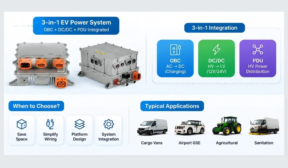
• OBC + DC/DC integrated at 2 kW + 1 kW: a single unit of about 4.5 kg.
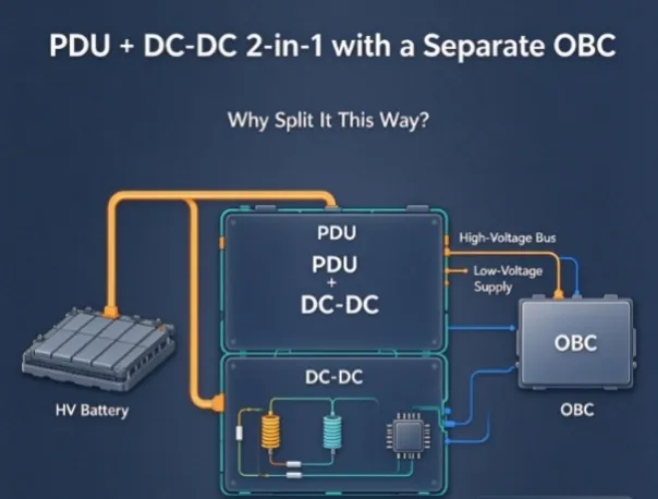
• Separate 3.3 kW OBC plus 500 W DC/DC: 4.3 kg plus 1.35 kg, on two brackets, with two harness runs and two cooling paths.
The integrated route wins on volume, bracket count and assembly time; the separate route wins on the ability to replace one function and keep the vehicle in service. On a shared fleet where a non-charging vehicle is a lost revenue day, that second point is worth more than the kilogram. On a private vehicle where the charger is a warranty item, it usually is not.
Run that comparison inside your own geometry rather than on these figures - 3D models and drawings covers how to do it, and the qualitative trade-offs are set out in the power-level selection guide for light electric vehicles.
Matching the Charger to a Small Pack
A small pack changes charging behaviour in a way worth designing around.
At 0.8C or above, a micro-mobility pack reaches its absorption voltage quickly and spends a long tail at reducing current. The total charge time is then dominated by the tail, not by the bulk phase. Doubling charger power can shorten the bulk phase and leave the total almost unchanged, while doubling the thermal load and the input current.
The practical consequence: measure the actual charge profile end to end before assuming more power means more availability. If the vehicle's duty cycle is a nightly charge of six hours, a 2 kW charger on a 4 kWh pack is sufficient, and the money is better spent on a converter that survives the thermal environment.
Product Mapping
Platform | Integrated option | Separate option |
48 V | — | |
72 V | ||
96 V | ||
Portable / removable | — |
A portable unit is worth considering where the vehicle has no reliable charging point: it moves the charging hardware to wherever the socket is, at the cost of a connector the user handles. For scooter and motorcycle platforms specifically, see OBCs for electric motorcycles and scooters.
Frequently Asked Questions
Is a 3.3 kW charger too large for a micro-mobility vehicle?
Not electrically - the charger limits itself to what the battery accepts. It is too large in volume, mass and input current for a platform that charges from a 110 V domestic socket, where it will deliver roughly half its rating. Size to the supply and the pack, not to the largest number in the catalog.
Can I use a 48 V charger on a 72 V system, or the reverse?
No. The output window is tied to the platform: a 48 V unit delivers roughly 50-105 V, a 72 V unit a different window again, and neither will correctly charge a pack outside its range. Voltage class is a hard constraint that precedes every other comparison.
Does the charger need to be liquid-cooled in a sealed compartment?
Rarely at this power level. Air cooling with a genuine intake and exhaust path is adequate up to the power levels micro-mobility vehicles use, and it avoids a coolant circuit on a vehicle that has none. If the compartment cannot be ventilated at all, the mounting surface becomes the thermal path and the unit choice has to follow from that.
Conclusion
On a micro-mobility platform the charger is a large component by ratio, so selection is driven by volume, mass, auxiliary load and the actual supply at the point of use - not by headline charging power. Pick the voltage class first, size the converter to peak rather than to margin, read the 110 V line in the datasheet before committing to a power level, and give the thermal path real space.
Working on a light or micro-mobility platform and comparing options? Send your battery voltage, pack capacity, auxiliary load peak and the supply available where the vehicle charges; our engineering team will match the platform to it.
About Echelon Charger
Echelon Energy Technology specializes in onboard chargers, DC/DC converters, and integrated EV power solutions for commercial and specialty electric vehicles.
For technical discussions, product selection, or OEM/ODM cooperation:
✉️ Email: nancy@tici-energy.com 💬 WhatsApp: +86 18114665311