
01 / Charging1
Onboard Charger (OBC)
Converts AC grid power into a controlled DC charge for the traction battery, following the CC-CV profile the BMS asks for.
AC in, DC out
OBC + DC-DC + PDU IN ONE UNIT
A 3-in-1 unit puts the onboard charger, the DC-DC converter and the high-voltage power distribution unit in a single housing with one cooling circuit and one high-voltage node. Fewer interfaces, less volume, one supplier to answer for the whole chain.
WHAT THE THREE FUNCTIONS DO
Each function has a distinct electrical role. Combining them removes duplicated housings, duplicated high-voltage connectors and duplicated interlock loops, but the design still has to keep each stage thermally and electrically separate.
Converts AC grid power into a controlled DC charge for the traction battery, following the CC-CV profile the BMS asks for.
Steps the high-voltage bus down to the 12 V rail that runs controllers, lighting, pumps and fans while the vehicle is driving.
Feeds and protects the high-voltage branches: traction, air-conditioning compressor, PTC heater and quick-charge inlet, each with its own interlock.
All three stages sit on one coolant path, so the enclosure is sized by the combined thermal load rather than three separate worst cases.
Battery, motor controller and charger connect through a single distribution point instead of a harness that loops between three separate units.
Charging, conversion and distribution are validated together against one document, which removes the boundary disputes between three vendors.
WHEN 3-IN-1 IS THE RIGHT ANSWER
Integration is not automatically better. The decision follows the vehicle's installation volume, its variant strategy and who owns the thermal problem.
When the platform has no room for three separate housings and three sets of high-voltage connections, a single enclosure buys back real space.
If charging power, auxiliary load and distribution branches are fixed for the life of the platform, combining them does not create a variant trap.
One unit means one test plan, one failure report and one party responsible when charging, conversion and distribution interact badly.
If one variant charges at 3.3 kW and another at 6.6 kW while the distribution needs stay identical, integrating every variant is wasteful.
A charger that runs hard during charging and a converter that runs hard while driving have different thermal peaks. Sharing one housing forces a compromise.
If field replacement is expected to swap one function at a time, a combined unit turns a small repair into a whole-unit replacement.
3-IN-1 UNITS IN PRODUCTION
Both units are in series production. Electrical settings, CAN behaviour, connectors and enclosure details can be adapted to your platform.

320 V liquid-cooled unit with 6 kVA AC output for auxiliary loads. 200-460 Vdc battery bus, 178 A auxiliary rail.

96 V and 320 V air-cooled unit for light commercial and specialty platforms. 34 A or 12 A charging current depending on platform.
OTHER PLATFORMS TO CONSIDER
A 2-in-1 keeps charging and conversion together without the distribution block. A standalone OBC stays independent of everything else. Both leave room for variant strategy.
96 V and 320 V platforms. Charging and auxiliary conversion in one unit without the PDU.
72 V, 96 V and 320 V entry-level 2-in-1 for cargo vehicles and utility platforms.

Charging only, 96 V and 320 V, IP67 and forced-air cooling. Leaves distribution to the vehicle.

V2G and V2L capability with a 3 kW DC-DC for 360 V liquid-cooled platforms.
RELATED READING
Longer technical articles on when to integrate, how to compare a 2-in-1 against a 3-in-1, and what a sample evaluation should prove.
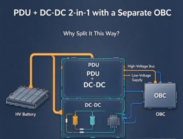
Why some EV platforms combine PDU with DC-DC and keep the OBC standalone: thermal duty cycles, variant flexibility, HV routing and the interfaces to agree.
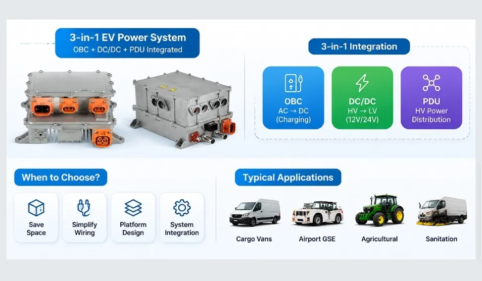
When should EV OEMs choose a 3-in-1 power system? Learn how OBC, DC-DC converters and PDUs work together, with key considerations for commercial and specialty EV integration.
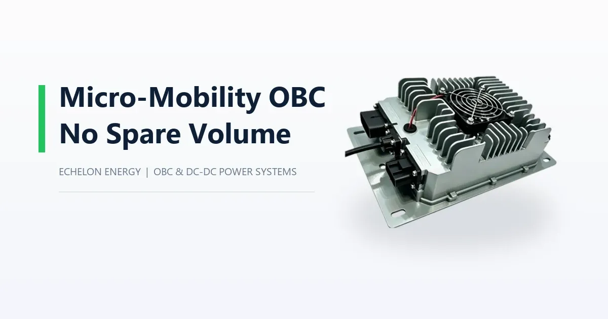
On a micro-mobility platform the charger is a measurable share of the vehicle. Voltage class from 48 V to 96 V, converter sizing, the 110 V derating trap and thermal limits.