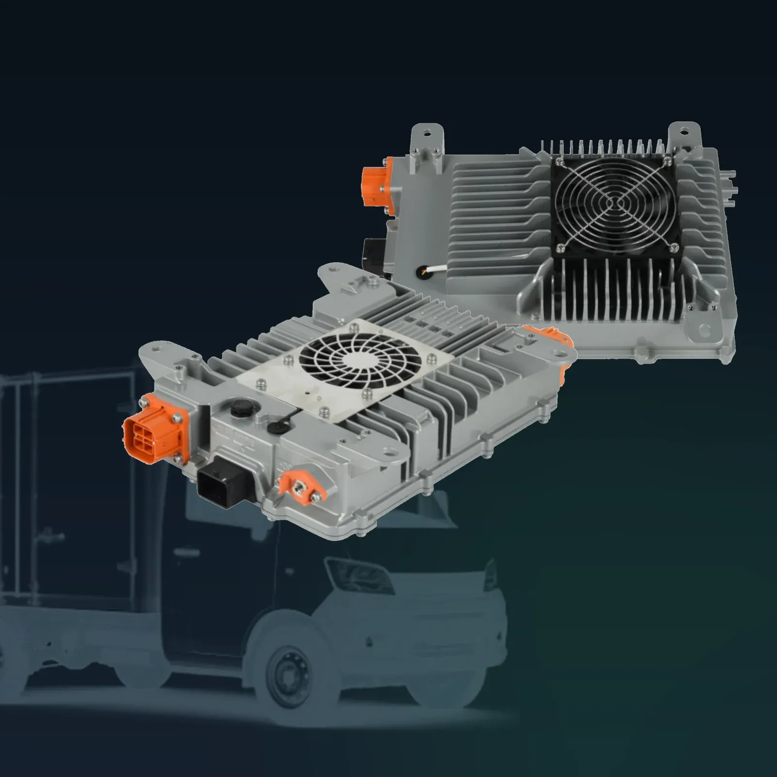
Oct 23, 2026EV System Integration & Architecture
OBC & DC-DC Enable Pin Requirements: Hardware vs CAN Control
How OBC and DC-DC enable control works: when a hardware enable is required, when CAN is enough, and why the 12 V enable cannot be replaced by a bus command.
When a 2-in-1 OBC and DC-DC unit goes into a light electric vehicle, an agricultural robot, an electric snowmobile or an L7 special vehicle, the enable interface is one of the first integration questions that comes up. Different OEMs and system integrators run different control architectures: some use discrete hardware enable signals, while others rely on the CAN bus to cut harness wiring.
The two functions inside a 2-in-1 unit do not answer this question the same way. The OBC enable is configurable. The DC-DC enable is not. Getting that distinction wrong during harness design usually shows up later as a power-up sequence fault or an unexpected standby current, so it is worth settling before the harness drawing is released.
What does the OBC enable pin actually control?
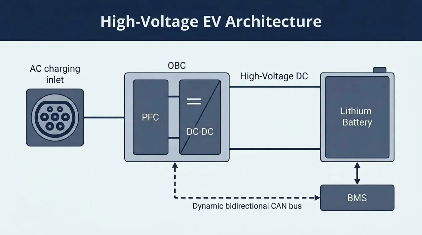
The OBC enable tells the charger when it is allowed to start an AC charging session. It is a permission signal, not a charging-current command: the current profile itself is negotiated with the BMS over CAN.
Because the OBC is only active when the vehicle is plugged in and the pack is ready, the enable method is largely a matter of vehicle architecture rather than electrical necessity. For that reason there is no mandatory enable pin for the OBC in our general specification; the control method is configured to match the customer's system design.
Option | How it works | Typical use |
Hardware enable (standard) | Discrete signal from the VCU or BMS switches the OBC on | Most vehicle platforms today |
CAN bus enable (optional) | OBC is switched on and off by CAN command | Projects minimising wire count |
Why does the DC-DC converter need a 12 V hardware enable?
The DC-DC stage supplies the vehicle's 12 V low-voltage network. That network powers the controllers, the BMS itself, the instrument cluster and the telematics unit, which means the DC-DC has to reach a defined state early in the power-up sequence, before the CAN bus is necessarily alive.
Our standard design therefore requires a 12 V hardware enable as a prerequisite for DC-DC operation. This is a baseline requirement rather than a configurable option, and it exists for three reasons:
A defined power-up sequence. The 12 V rail comes up in a known order instead of depending on bus traffic.
Controlled standby current. Without a hardware gate, the converter could draw quiescent current in states where the vehicle expects none.
Undervoltage protection. A hard enable prevents the converter from attempting to start into a rail that is not yet stable.
Can a CAN command replace the hardware enable?
For the DC-DC, no. CAN enable and disable commands are available and supported, but they work as an upper-layer control instruction on top of the 12 V hardware enable. The bus command tells the converter what the vehicle wants; the hardware signal establishes that the vehicle is electrically ready for it.
This is the point where integration teams most often expect a shortcut. A design that removes the 12 V enable and relies purely on CAN will not match our standard DC-DC behaviour, and it forfeits the sequencing guarantee described above. If the goal is fewer wires, the realistic saving is on the OBC side, not the DC-DC side.
Function | Hardware enable | CAN enable command | Can CAN replace hardware? |
OBC | Standard option | Supported as an alternative | Yes, at configuration stage |
DC-DC | Required | Supported as an upper-layer command | No, both are needed |
What changes when the unit is used in an agricultural robot or an L7 vehicle?
The enable logic does not change with vehicle class, but the consequences of getting it wrong do. Agricultural robots and L7 special vehicles often run unattended charge cycles or start from a battery isolator rather than a key switch, so the power-up order matters more than on a vehicle where a driver is present at every start.
In those programs it is worth confirming three points early: which node asserts the enable, what state the 12 V rail is in when the enable is asserted, and whether the vehicle expects the DC-DC to be live during charging. The answer to the third question frequently decides the harness topology.
Which documents are needed for HV connector assembly?
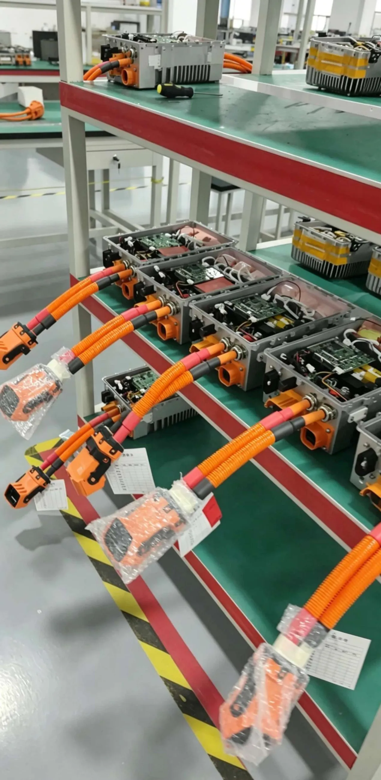
High-voltage connector assembly and crimping directly affect insulation safety and long-term reliability. A correctly specified connector that is crimped with the wrong tool, or terminated without following the housing manufacturer's procedure, can pass a bench check and still fail in service.
On request we provide official HV connector assembly instructions so that harness manufacturers and system integration teams can prepare cables and connectors correctly. This is a supporting technical service for integration projects rather than a substitute for the connector maker's own documentation.
For a new program, the usual document set is:
Pin definition table for the specific model variant
Power sequence description covering enable, pre-charge and ready states
CAN matrix or DBC file for the vehicle network
HV connector assembly instructions
Which 2-in-1 platforms does this apply to?
The enable rules above apply across the integrated platform family. The table below summarises the units most often specified for light EVs, agricultural machines and special-purpose vehicles.
Platform | Voltage window | DC-DC stage | Typical application |
50-105 Vdc (72 V) / 64-128 Vdc (96 V) / 240-480 Vdc (320 V) | 14 V, 72 A, 1000 W | Light EVs, agricultural machines, L7 vehicles | |
64-128 Vdc (96 V) / 240-480 Vdc (320 V) | 9-16 Vdc, 110 A rated / 132 A peak, 1500 W | Light commercial vehicles, utility platforms | |
200-470 Vdc | 9-32 Vdc auxiliary rail | Multi-shift fleets, V2L and V2G | |
60-128 Vdc (96 V) / 195-450 Vdc (320 V) | 9-16 Vdc, 72 A, 1000 W | Where on-board distribution protection is needed |
All four use CAN bus communication and are rated IP67. The enable behaviour described here is common to the family, so a program that moves between voltage variants does not need to redesign its control interface.
What to send us for a pin definition review
A pin-level answer needs four inputs: the model variant you intend to use, which node asserts the enable in your architecture, the state of the 12 V rail at that moment, and whether the DC-DC must run during charging. With those, we can confirm the wiring against the platform rather than against a generic datasheet.
The RFQ checklist covers the wider input set for a program, and our OEM/ODM page explains how variants are configured. For background on message design, see how CAN communication improves charger integration and what to confirm before integrating an OBC with CAN.
FAQ
Is there a mandatory enable pin on the OBC?
No. There is no mandatory enable pin for the OBC in our general specification. Hardware enable from the VCU or BMS is the standard option, and CAN bus enable is available as an alternative, selected according to the vehicle's control strategy.
Can I run the DC-DC without a 12 V hardware enable?
Not on our standard design. The 12 V hardware enable is a prerequisite for DC-DC operation. CAN enable and disable commands are supported, but they act as an upper-layer instruction on top of the hardware enable rather than replacing it.
Why is the DC-DC requirement stricter than the OBC requirement?
The DC-DC feeds the 12 V network that the controllers and the BMS itself depend on, so it has to reach a defined state early in the power-up sequence. The OBC only runs when the vehicle is plugged in and the pack is ready, which leaves more freedom in how it is enabled.
Does CAN enable reduce harness cost?
On the OBC side it can, by removing a discrete signal wire. On the DC-DC side the 12 V hardware enable remains, so the saving there comes from other parts of the harness rather than from removing that signal.
Are HV connector assembly documents included by default?
They are provided on request as a supporting service for integration projects. The connector manufacturer's own documentation still governs the crimp specification.
Does this apply to a 400 V or 800 V project?
The enable logic is the same at any voltage class; what changes is the connector family and the isolation requirements. Confirm the variant and the connector type when requesting the pin definition table.
About Echelon Charger
Echelon Energy Technology specializes in onboard chargers, DC/DC converters, and integrated EV power solutions for commercial and specialty electric vehicles.
For technical discussions, product selection, or OEM/ODM cooperation:
Email: nancy@tici-energy.com
WhatsApp: +86 18114665311
For pin definition tables, power sequence descriptions, CAN matrix or DBC files, use our contact page.