
CAN Communication and BMS Integration Checklist for OBC
CAN communication and BMS integration checklist for OBCs: messages, baud rate, wake-up, diagnostics, and fault handling for EV OEM engineers. Read more.
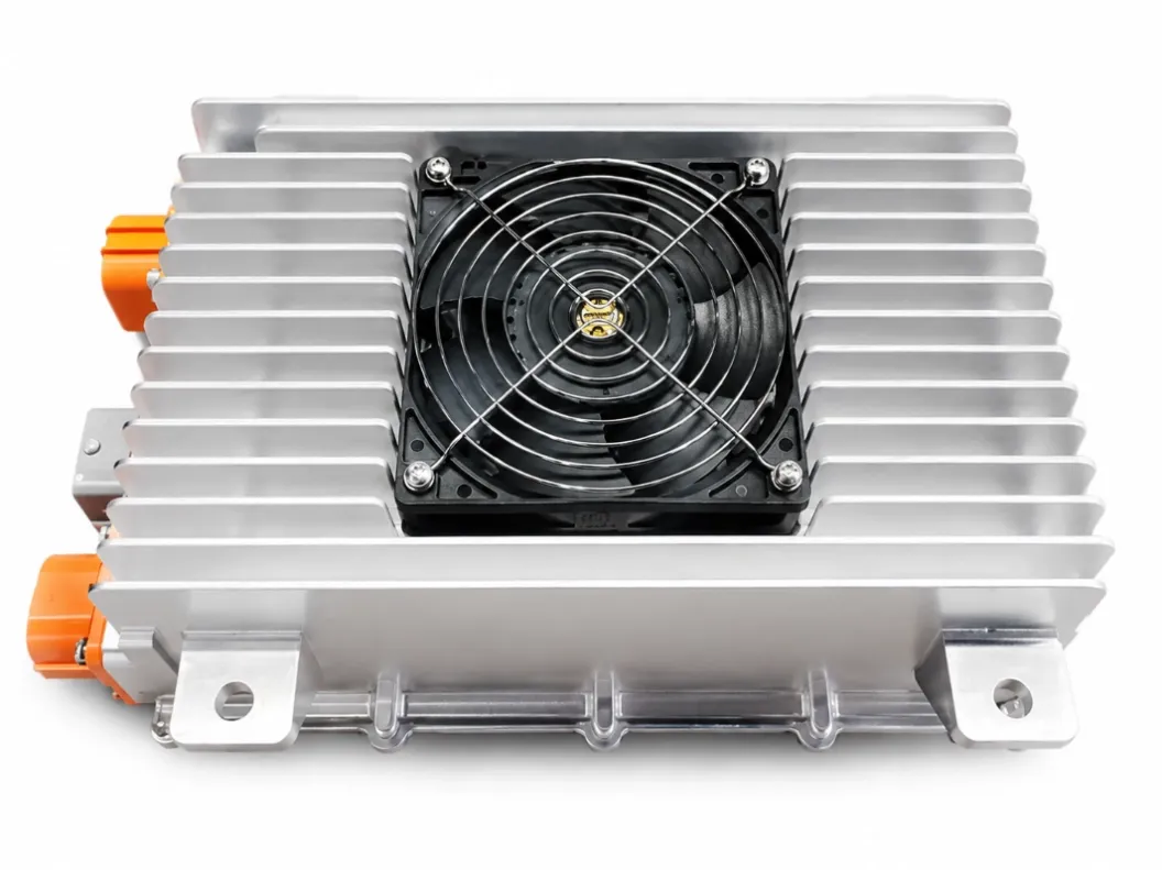
An on-board charger (OBC) that charges correctly on a bench can still fail in a vehicle if it does not communicate correctly with the battery management system (BMS) and the vehicle control unit (VCU). CAN communication is not an afterthought. It is the interface that decides whether charging starts, how fast it runs, when it stops, and what happens when something goes wrong.
This guide is a checklist for EV OEM engineers integrating an OBC, using Echelon's CAN-bus OBCs as examples. Use it in design reviews before the hardware is frozen.
- The OBC, BMS, and VCU must agree on CAN version, baud rate, message set, and who controls charging — before hardware is locked.
- The BMS controls the charge profile. The OBC follows it. Do not let the OBC impose a fixed profile.
- Wake-up, sleep, and standby current affect the 12 V battery and the vehicle off-state. Test them early.
- Diagnostics, fault codes, and fault recovery must be defined. A fault that requires a power cycle in the field is a service problem.
- Get the CAN database file and protocol document before design freeze. Late integration work is far more expensive than an early hardware change.
What CAN Does in an OBC System
Controller Area Network (CAN) is the vehicle bus that carries messages between the OBC, BMS, VCU, and other controllers. In a typical commercial EV, CAN carries:
- Charge enable and charge request from the VCU or BMS
- Battery voltage, current, temperature, and state of charge from the BMS
- Charge current and voltage limits from the BMS
- OBC status, output voltage and current, temperature, and fault codes
- Wake-up and sleep commands, and diagnostic messages
Echelon OBCs use CAN-bus communication. The 6.6 kW AC/DC Dual-input OBC lists CAN 2.0, AUTOSAR architecture, and UDS diagnostics. Confirm the CAN version, baud rate, and diagnostic support for the specific model you select — do not assume every model has the same CAN feature set.
Checklist 1: Physical Layer and Bus
- ☐ CAN version: CAN 2.0 or CAN FD? Confirm the OBC supports the version your VCU requires. If your VCU uses CAN FD and the OBC only supports CAN 2.0, integration will fail or need a gateway.
- ☐ Baud rate: What baud rate does the OBC use — for example 250 kbps or 500 kbps? Is it fixed or configurable? Does it match the bus it will join?
- ☐ Termination: Is termination internal or external? What is the termination resistance, and where is it in the harness?
- ☐ Connectors and wiring: Which connector carries CAN High and CAN Low? What is the pinout, wire gauge, and maximum bus length? Is CAN isolated from high voltage?
- ☐ Bus load: How many messages per second does the OBC send at full rate? What is the total bus load with all nodes? A bus that is over 70-80% loaded can drop messages under peak conditions.
- ☐ Number of CAN channels: Does the OBC have one CAN channel or two? Does it need a dedicated charging CAN or can it share the vehicle CAN?
Ask for the physical-layer specification and the harness drawing. Do not rely on a verbal 'it has CAN' — that tells you nothing about compatibility.
Checklist 2: Message Set
Get the CAN database file (DBC) and the protocol document. Then check:
- ☐ Messages sent by the OBC: status, output voltage, output current, temperature, fault codes, and charge state. What is the cycle time for each? What happens if a message is missed?
- ☐ Messages received by the OBC: charge enable, charge current request, voltage limit, and stop command. Who sends each message — BMS or VCU?
- ☐ Signal definitions: units, scaling, offset, range, and invalid values for every signal. A current signal in 0.1 A steps is not the same as one in 1 A steps.
- ☐ Message IDs and priorities: are the IDs fixed or configurable? Do they conflict with existing IDs on the bus?
- ☐ Timeouts: how long does the OBC wait for a BMS message before it faults or stops charging? What is the timeout for VCU messages?
- ☐ Endianness and byte order: Intel or Motorola format? A byte-order error can turn a 100 A request into a nonsense value.
Test the message set on a bench with a CAN tool before you test in the vehicle. Log every message, and compare it to the DBC.
Checklist 3: Charging Control — Who Decides What?
The most common integration failure is unclear control authority. Write down, in one table, who controls each decision:
| Decision | Controlled by | How it is communicated |
|---|---|---|
| Charge start | VCU / BMS / OBC? | CAN message, AC plug detection, or both? |
| Charge current request | BMS, based on SoC, temperature, and cell voltage | CAN message, updated how often? |
| Charge voltage limit | BMS | CAN message, with what range? |
| Charge termination | BMS, OBC, or both? | CAN message, or voltage / current threshold? |
| Derating on temperature | BMS, OBC, or both? | Which temperature, and what derating curve? |
| Fault stop | OBC, BMS, or VCU? | CAN message, hardwired signal, or both? |
If two controllers can both stop charging, define the priority. If the BMS requests 0 A, does the OBC stop immediately or ramp down? If CAN is lost, does the OBC stop, continue at the last request, or go to a safe default? The answer must be written down, not left to 'it should stop.'
Checklist 4: BMS Integration
The BMS is the authority on the battery. The OBC must respect it.
- ☐ Charge profile: does the OBC follow the BMS CC-CV profile, including taper and temperature derating? Ask for the profile in a table, not just in words.
- ☐ Cell and pack limits: maximum charge voltage, maximum charge current at different SoC and temperatures, and minimum temperature for charging. Are these limits in the CAN messages or in the OBC firmware?
- ☐ Pre-charge and contactor control: who closes the high-voltage contactor, and in what sequence? Does the OBC need a pre-charge signal from the BMS?
- ☐ Insulation and safety: how is insulation monitoring handled? Who detects a high-voltage fault, and how is it reported on CAN?
- ☐ State of charge and health: does the OBC need SoC or state of health for its own control, or does it only report what the BMS sends?
Get the BMS charge specification in writing, and have the OBC supplier confirm in writing that the OBC can follow it. A verbal confirmation is not enough for a safety-related interface.
Checklist 5: Wake-Up, Sleep, and Standby
- ☐ Wake-up on AC plug-in: how does the OBC wake when AC is connected? Does it wake the VCU and BMS, or does the VCU wake it?
- ☐ Wake-up on CAN: can the OBC be woken by a CAN message? What is the wake-up pattern?
- ☐ Sleep: when does the OBC go to sleep after charging ends? What is the delay, and what triggers it?
- ☐ Standby current: what is the OBC standby current when the vehicle is off? A high standby current can drain the 12 V battery over a weekend.
- ☐ 12 V supply: does the OBC need a 12 V supply to wake, or can it wake from AC alone? What happens if the 12 V battery is flat?
Test wake-up and sleep in the vehicle, with the real 12 V battery and the real harness, not just on a bench with a power supply. Standby problems are often found only in the vehicle.
Checklist 6: Diagnostics and Fault Handling
- ☐ Fault codes: what fault codes does the OBC report, and what does each code mean? Is there a fault-code list with causes and recommended actions?
- ☐ UDS diagnostics: the dual-input 6.6 kW OBC lists UDS diagnostics and AUTOSAR. Confirm whether UDS is available on your model, which services are supported, and how to access them.
- ☐ Fault recovery: after a fault, does the OBC recover automatically, require a CAN reset, require a key cycle, or require a power cycle? How long does recovery take?
- ☐ Fault logging: does the OBC log faults with a timestamp? Can the log be read over CAN or UDS, or does it need a separate tool?
- ☐ Software updates: can the OBC firmware be updated in the vehicle, over CAN or UDS? What is the update procedure, and what happens if an update fails?
- ☐ Calibration and configuration: are CAN IDs, baud rate, voltage limits, or current limits configurable? How are they set — in the factory, by the OEM, or in the field?
A fault that can only be cleared by removing the unit is a service cost. A fault that is not logged is a diagnostic cost. Both should be known before volume production.
Checklist 7: Testing Before Volume
Do not go to volume on the basis of a datasheet alone. Test:
- Bench test: OBC + BMS simulator + CAN tool. Verify every message, every signal, and every timeout.
- Vehicle test: OBC in the vehicle, with the real BMS, VCU, harness, and AC supply. Test charge start, charge stop, derating, fault injection, and CAN loss.
- Environmental test: charge at the highest and lowest expected temperatures, with the real cooling and mounting. Check derating and fault behaviour.
- Long-duration test: charge for the full window, repeatedly, over several days. Check for intermittent CAN errors, fan behaviour, and standby drain.
- Service test: simulate a fault, clear it, and confirm the vehicle can charge again without special tools, if that is the intended service procedure.
Record the test results against the checklist above. Any item that is not tested is an open risk.
Common Integration Mistakes
- Assuming CAN FD and CAN 2.0 are interchangeable. They are not. Confirm the version.
- Leaving charge control authority undefined. If both the BMS and the OBC can stop charging, define who has priority.
- Forgetting CAN loss. The OBC must have a defined safe behaviour if CAN is lost during charging. 'It should stop' is not a specification.
- Testing only at room temperature. CAN timing, derating, and wake-up can all change with temperature.
- Not getting the DBC file. Without the DBC, you cannot verify the message set. Get it before design freeze.
Related reading: How to Choose an On-Board Charger (OBC) for Commercial EVs · What Is a Bidirectional OBC? V2L, V2V, and V2G Explained · OBC RFQ Checklist: What EV Manufacturers Should Provide Before Requesting a Quotation
FAQ
What is the difference between CAN 2.0 and CAN FD?
CAN FD (Flexible Data-rate) can carry larger payloads and higher data rates than classic CAN 2.0. A CAN FD controller can usually talk to a CAN 2.0 node, but not at FD rates. Confirm which version your VCU and OBC both support, and at what baud rate.
Who should control charge termination — the OBC or the BMS?
In most designs, the BMS is the authority, because it knows cell voltage, temperature, and SoC. The OBC follows the BMS request and provides its own protection as a backup. Confirm this division in writing for your system.
What happens if CAN is lost during charging?
That must be defined in the specification. Common safe behaviours are to stop charging, ramp down to a safe current, or hold the last request for a short timeout and then stop. Confirm the behaviour for the specific model with the supplier.
Do I need UDS diagnostics for an OBC?
Not always, but UDS makes service and fault diagnosis much easier, especially in a fleet. If UDS is listed for the dual-input unit, ask whether it is available on your model and which services are supported.
What documents should I ask for?
Ask for the CAN database file (DBC), the CAN protocol document, the fault-code list, the charge-control specification, the wake-up / sleep specification, and the UDS diagnostic specification, for the specific model. Confirm lead time for any custom CAN configuration directly with the engineering team.
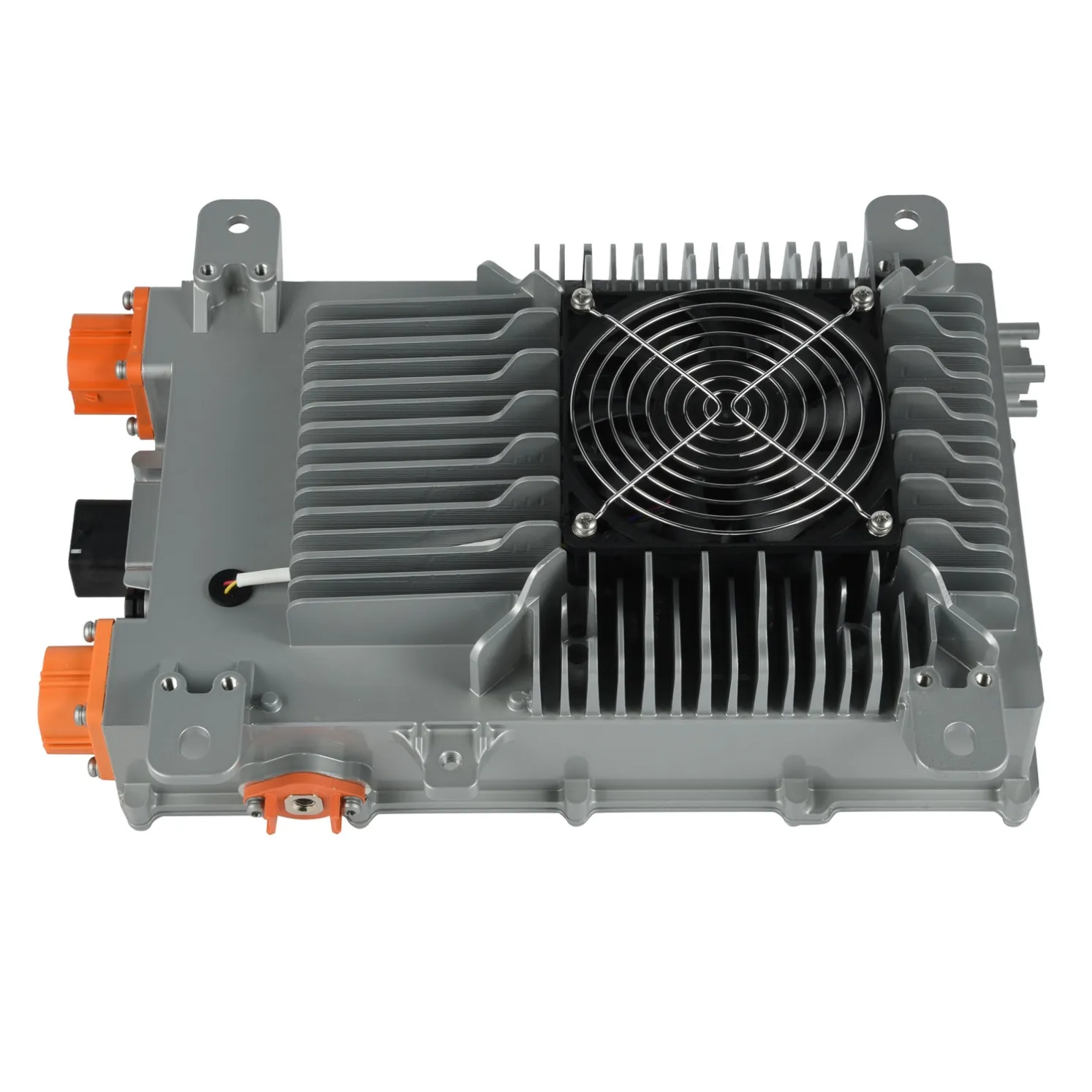
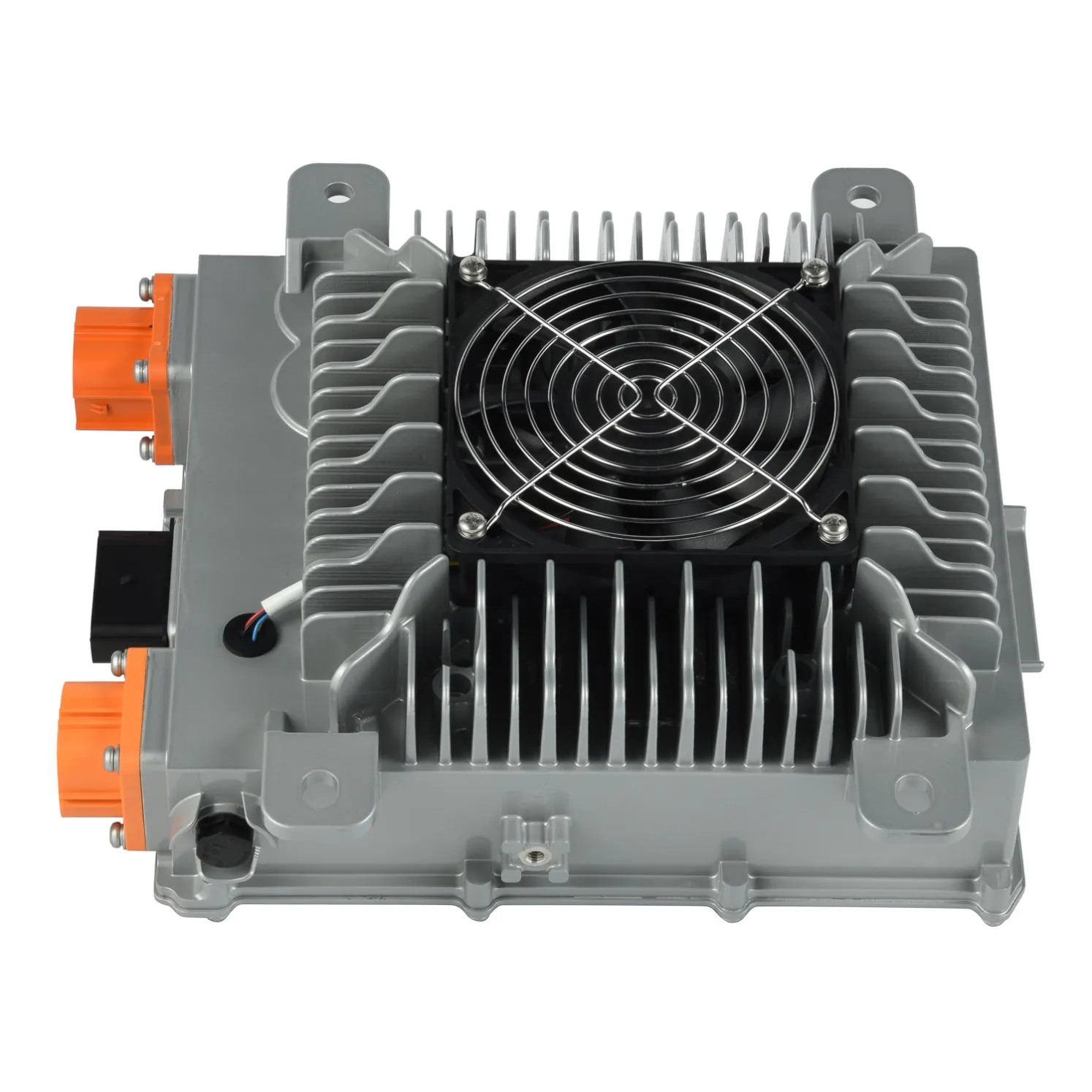
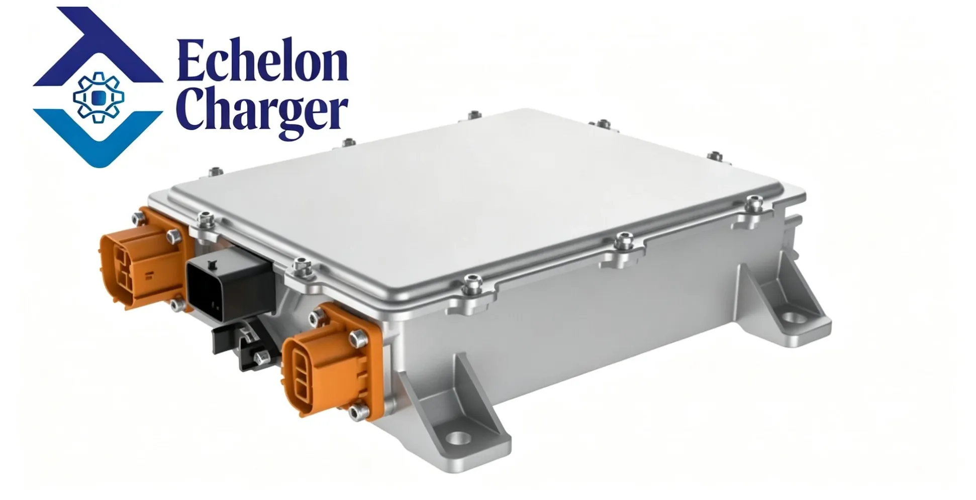
Related Echelon Products
See the full range on the products page.

Next Step
Send the Echelon engineering team your VCU CAN version and baud rate, your BMS charge profile, and your wake-up / sleep requirements, and request the DBC file, protocol document, and fault-code list for the matching OBC. Review them against the checklists above before you freeze the hardware.
To start, share your vehicle and battery requirements through our contact page, and see how a custom programme is scoped on our OEM/ODM page. Before requesting a quotation, the OBC RFQ checklist lists the inputs that let Echelon quote accurately in one pass.
About Echelon Charger
Echelon Energy Technology specializes in onboard chargers, DC/DC converters, and integrated EV power solutions for commercial and specialty electric vehicles.
For technical discussions, product selection, or OEM/ODM cooperation:
Email: nancy@tici-energy.com
WhatsApp: +86 18114665311
